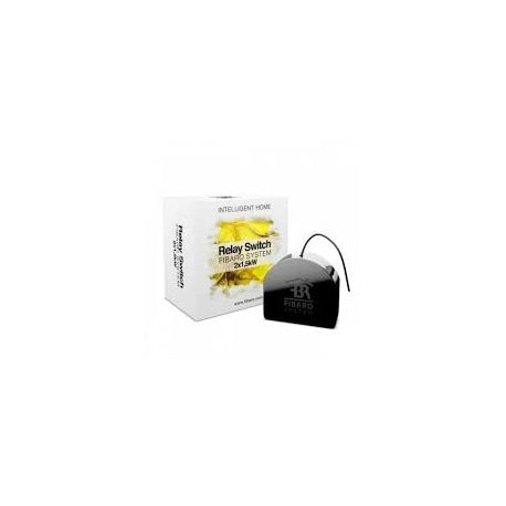
Features
- Compatible with any Z-Wave Controller
- Advanced microprocessor control
- Executive element – electromagnetic, micro-gap relay switch
- May be oparated by momentary or toggle switches
- To be installed in wall switch boxes of dimensions allowing for installation, conforming to provisions of applicable regulations

Technical Data
- Power supply: 110-240 V AC, 50/60 Hz
- Rated load current (resistive load): 6.5A per channel,10A total current
- Power consumption: up to 0.8W
- Power output (resistive load): 2x1500W for 240V AC2x750W for 120V
- ACIn accordance with EU standards: RED 2014/53/EURoHS 2011/65/EU
- Operational temperature: 0-35°C
- Active element: micro-gap relay switch μ
- Durability (resistive load, 6.5A): 200 000 switches
- For installation in boxes: Ø ≥ 50mm, depth ≥ 60mmRadio protocol:Z-Wave
- Radio signal power: up to 1mW
- Radio frequency: 868.4 MHz EU;908.4 MHz US;921.4 MHz ANZ;869.0 MHz RU;865.2 MHz IN;
- Radio transmits power: up to -1 dBm (EIRP)
- Range: up to 50 m outdoors up to 30 m indoors (depending on building materials)
- Dimensions: (L x W x H)):42.50 x 38.25 x 20.30 mm
Frequently Asked Questions
Can this module be DC supplied?
No, only previous generation of the device was able to do so.
I want to control the lighting but I do not have Neutral wire. Can I connect Relay Switch to such circuit?
No. The Relay Switch needs to be connected to Neutral Wire. To control circuits where there is no Neutral wire at the switch location please refer to the Dimmer module.
Can I control non-potential output by the Relay Switch module?
Yes, you can – the relay is volt free by default.
What are association groups 1, 2 and 3 for?
Group 1 is assigned to S1, Group 2 is assigned to S2 and Group 3 is only used for reporting module’s state to the controller.
What are S1, S2 for?
These terminals are designed to be connected to the switch. S1 is designed to control O1 output, S2 to control O2 output.

